June 30, 2017

So you want to get a part made? – Costly processing mistakes can be made without a good design. By keeping to some simple rules of part design should give you a part that is not only easier to manufacture and assemble, but will withstand the test of time.
Design
A strong mould design gives high volume quality, so exacting standards must be met not only in the cavities, but in the design of the mould components. Size and placement of gates should be taken into consideration to allow for correct melt flow and to avoid insufficient fill problems. Vents allow the air that is displaced by the melted resin to escape the tool, so again, size and position are key factors to avoid flashing from escaping material, short shots from improper fill or burn marks. If you missed it, we wrote a blog a few months ago with some helpful tips; the ten most common moulding issues and solutions.
It is essential the following key design factors are taken into account to avoid such things as; shrinkage, warpage and twisting, cracking and voids:
Wall Thickness
Keeping uniform thickness of walls allows the mould cavity to fill more easily as the molten plastic will flow into areas of least resistance. If you have a part with both thick and thin walled sections, depending on gate placement, the molten plastic will flow into the thick walled area first, leaving the thin areas not filling and packing properly. In addition the thinner sections cool first, so shrinkages, voids and sinking defects, along with warping or twisting can occur as the thick sections cool. Sharp corner or angle changes also impede flow, so corners should have a curve versus an angle and the radius should be consistent on the inside and outside of the wall creating uniform thickness.
If, due to design limitations your part design does not have a consistent wall thickness, there are several things you can do to avoid these problems. Design it so that the change in thickness is as gradual as possible. Gate placement to ensure the cavity fills correctly. Coring or hollowing out thicker areas to help uniformity.
Weld Lines
Possibly the most common and difficult defect to eliminate. Weld lines are formed when two material flows come together. The overall flow pattern of the plastic as it enters the mould cavity is most important to weld line strength. Minimising flow interruptions and placing them so that the flow fronts are allowed to meet and flow some distance together to merge properly, are the keys to optimising part performance. Computer aided simulations can help designers determine where the weld line will occur. A non uniform flow front due to non uniform wall thickness can be remedied by the use of gating. It is also critical to properly vent the area at, and near the end of the weld line.
Gate Placement and Size
Gates are key to ensuring your mould fills uniformly as they direct the plastic flow throughout the part. Choosing the type of gate and placement, eg placing the gate so that the weld line location is not in an area of the part that will see high stress during use, will have major impact on part quality. Wall thickness and geometry dictate placement, size and the number of gates used and their location should minimise the flow length to avoid flow marks. Gates that flow from thick to thin walls will fill and pack better than gates that flow from thin to thick walls.
Vent Placement
Vents allow the gas (air) in the mould cavity to escape without causing burning of the resin. It is critical to properly vent the area at and near the weld line. The addition of a flow tab allows the flow fronts to knit better and act a a vent for any trapped air when the flow fronts meet. Bosses (used for attaching fasteners like screws or accepting threaded inserts), ribs (used to increase the bending stiffness of a part without adding thickness) etc should be in the direction of the flow to aid filling and venting. Other methods to reduce or evacuate trapped air are porous steel inserts, vented core pins or vacuum venting.
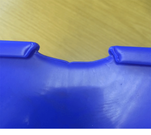
The following table lists a few common plastic part defects to look out for;
| Colour/Additive Defects | Processing Defects | Mould Design/Maintenance |
| Colour streak | Blistering | Drag Marks |
| Delamination | Burn Marks | Flash or Burrs |
| Splay Marks | Sink Marks | Jetting |
| Discolouration | Flow Marks | Warping |
Tools should be built to last for years and building a quality precision mould will be an investment for your company. Do you need any further information? Let us know by contacting our sales and technical team, who are always happy to help.
SEE ALSO:
PART 1 – DESIGNING AND BUILDING THE TOOL
July 04th, 2019
Leading technical injection moulder, Counterplas, has set ambitious growth targets, buoyed by their recent move to a large new facility in South Staffordshire.
February 02th, 2018
Counterplas have invested in the latest Rhino version 5 software, widely acclaimed as the world’s most robust 3-D development platform for specialty modelling, rendering, analysis, and fabrication tools.
January 08th, 2018
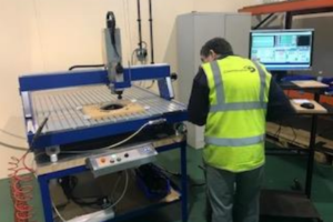
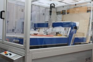
We have invested in a new CNC routing system for production of illuminated bespoke street furniture for a new client in Germany. A ‘blank’ is injection moulded and then routed to provide one of 270 variants.