June 07, 2017

So you want to get a tool made? – as this can be the largest investment in the manufacturing process, getting it right is key. Build time can take time and a great deal of accuracy, so the following factors should be taken into consideration
Start by understanding the issues different plastics can create, as you may need to design around these to avoid issues with the end product for surface finishes, cracking, voids, cooling and venting, to name a few. If you missed it, we wrote a blog a few months ago describing the ten most common moulding issues and their solutions.
Design
A strong mould design leads to high volume quality, so exacting standards must be met not only in the cavities, but in the design of the mould components. Size and placement of gates should be taken into consideration to allow for correct melt flow and to avoid insufficient fill problems. Vents allow the air that is displaced by the melted resin to escape the tool, so again, size and position are key factors to avoid flashing from escaping material, short shots from improper fill or burn marks.
Types of plastic
Polymer choice is down to a number of different attributes – price, heat resistance, chemical resistance, shrinkage, flame-resistance, tensile strength, flexural strength. Remember to take into consideration plastics that are amorphous as these are less free-flowing but tend to shrink less, compared to crystalline or semi-crystalline plastics which flow better but have higher shrinkage rates. Plastic suppliers will give guidance on shrinkage, temperature and melt flow rates.
Cooling to maximise output
A well designed cooling system is key in helping the mould maintain a consistent temperature in order to avoid warping and shrinkage and keep cycle times to a minimum.
Ejecting mould parts
The placement of the ejector pins, type of ejection mechanism and cycle times should be calculated with precision to avoid defects. Size and position being determined by the shape, size and wall thickness of the part along with type of resin and mould finish.
Product sample
Creating a sample mould to produce a test run will save money and time in the long run, as any adjustments can be done at this stage thus ensuring your customer’s requirements are met at all times.
Tools should be built to last for years and building a quality precision mould will be an investment for your company. Do you need any further information? Let us know by contacting our sales and technical team, who are always happy to help.
SEE ALSO:
July 04th, 2019
Leading technical injection moulder, Counterplas, has set ambitious growth targets, buoyed by their recent move to a large new facility in South Staffordshire.
February 02th, 2018
Counterplas have invested in the latest Rhino version 5 software, widely acclaimed as the world’s most robust 3-D development platform for specialty modelling, rendering, analysis, and fabrication tools.
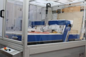
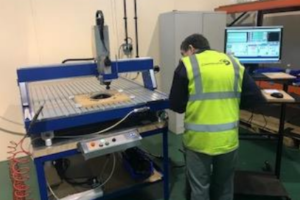
January 08th, 2018
We have invested in a new CNC routing system for production of illuminated bespoke street furniture for a new client in Germany. A ‘blank’ is injection moulded and then routed to provide one of 270 variants.