Back to Talking Points

The Ten Most Common Moulding Issues And Solutions

There are 4 areas that can cause poor quality plastic injection moulded parts:

  • PART DESIGN
  • TOOL DESIGN
  • PROCESS SET UP
  • MATERIAL QUALITY

It’s not unusual for product designers to blame the moulder for poor set up or tool designers for issues with the finished part, but it’s important to remember that mouldability of a part is dictated by PART DESIGN. A product designer must design a part for the manufacturing process that is fit for purpose to help reduce the common issues that can arise.

Take a brief look at the ten most common moulding issues and the various solutions to alleviate these problems. Please note this is only a short overview of the various issues and solutions, if you would like more information or have any specific questions please email us info@counterplas.co.uk

SHORTS

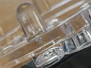
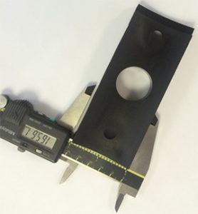
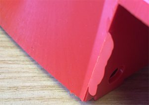
A short “shot” is the complete filling of a mould cavity which results in the production of an incomplete part. If a part short shots, the plastic does not fill the cavity.
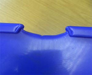
A short "shot" is the complete filling of a mould cavity which results in the production of an incomplete part.

SOLUTIONS:

Part Design

  • Aid material flow by increasing the thickness of thin sections

Tool Design

  • Check venting and increase where necessary
  • Check balance of tool if multi cavity
  • Increase size of runner system
  • Check location of gates

Process Setup

  • Increase polymer melt temperature
  • Increase mould temperature
  • Increase shot size
  • Increase injection pressure
  • Check for blockages in runner system or nozzle
  • Increase injection time

SINK MARKS

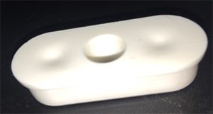
A Sink Mark can be defined as a depression, resembling a dimple or groove

A Sink Mark can be defined as a depression, resembling a dimple or groove, caused by excessive localized shrinking of the material after the part has cooled.

SOLUTIONS:

Part Design

  • Ensure one of the walls is between 60% and 70% of the mating wall thickness
  • Reduce thickness of features where sink occurs

Tool Design

  • Increase size of runner system
  • Check location of gates

Process Setup

  • Reduce melt temperature
  • Increase shot size
  • Increase injection pressure
  • Increase injection time
  • Increase cooling time
  • Reduce injection speed

STRESS WHITENING/CRACKS

White marks or cracks on the surface of a part.

SOLUTIONS:

Part Design

  • Add fillets where walls/features intersect
  • Check any living hinges

Process Setup

  • Increase mould temperature
  • Decrease injection pressure
  • Increase nozzle temperature

Material Quality

  • Check the chemical resistance of the material

VOIDS

They appear as bubbles or blisters and are pockets of trapped gas.

SOLUTIONS:

Part Design

  • Keep wall thicknesses uniform
  • Reduce part thickness

Tool Design

  • Check venting and increase where necessary
  • Increase size of runner system

Process Setup

  • Reduce melt temperature
  • Increase injection pressure
  • Reduce injection speed

Material Quality

  • Dry material to manufacturers specification

PARTS STICKING IN MOULD

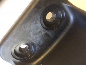
When parts do not eject properly from the mould

When parts do not eject properly from the mould

SOLUTIONS:

Part Design

  • Remove undercuts
  • Increase draft
  • Reduce textured surfaces or make them smoother

Tool Design

  • Evaluate ejector mechanism

Process Setup

  • Increase cooling time
  • Reduce injection pressure

UNDERSIZE PART

When parts are smaller than expected

When parts are smaller than expected

SOLUTIONS:

Part Design

  • Keep wall thicknesses uniform

Tool Design

  • Increase size of runner system

Process Setup

  • Increase injection speed
  • Reduce mould temperature
  • Increase injection pressure
  • Pack pressure too low

JETTING

Jetting can be defined as a ``snake-like'' pattern on the surface of a molded part, usually emanating from the gate area.

Jetting can be defined as a “snake-like” pattern on the surface of
a molded part, usually emanating from the gate area. It is indicative
of an undesirable turbulence and splitting of the flow front.

SOLUTIONS:

Part Design

  • Increase thickness of thin sections to aid material flow
  • Add fillet radii where walls or features intersect

Tool Design

  • Move the gate to a location that enables the flow to alter on entry
  • Increase size of gate

Process Setup

  • Reduce injection speed
  • Adjust melt temperature

WARPAGE

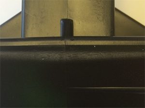
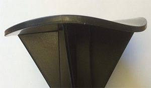
This is a dimensional distortion in a moulded product after it is ejected from the mould at the end of the injection moulding process.

This is a dimensional distortion in a moulded product after it
is ejected from the mould at the end of the injection moulding process.
You will see bending, twisting or bowing of a part.

SOLUTIONS:

Part Design

  • Thicken ribs
  • Reduce size of large flat surfaces by adding ribs.
  • Keep wall thicknesses uniform

Tool Design

  • Check location of gates
  • Increase size of gate
  • Check knockout design and operation
  • Improperly balanced multiple gates

Process Setup

  • Adjust injection pressure
  • Adjust melt temperatures
  • Check that core & cavity temperatures are balanced
  • Increase cooling time

WELD LINES AND FLOW MARKS

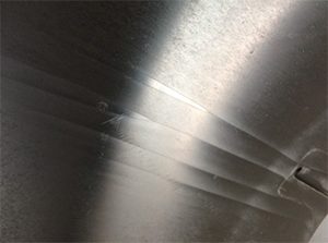
These are both a visual and a mechanical defect.

These are both a visual and a mechanical defect. They appear where the polymer meets the mould and are a result of turbulence.

SOLUTIONS:

Tool Design

  • Check location of gates
  • Increase size of runner system
  • Check venting and increase if necessary

Process Setup

  • Increase injection pressure
  • Increase melt temperature
  • Increase mould temperature
  • Check the mould for contamination or damage

FLASH

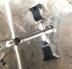
A thin layer of material is forced out of the mould cavity generally appearing around sealing faces and ejector pin location.

A thin layer of material is forced out of the mould cavity generally appearing around sealing faces and ejector pin location. This excess material remains attached to moulded product and normally has to be manually removed.

SOLUTIONS:

Tool Design

  • Check ejector pins and bores are within tolerances
  • Check shut-off faces of mould are aligned
  • Check venting and increase if necessary

Process Setup

  • Reduce injection pressure
  • Increase clamping force
  • Check mould for contamination
  • Reduce mould temperature
  • Reduce back pressure

Do you need any further information? Let us know by contacting our sales and technical team, who are always happy to help.


See Also

Counterplas Invests for Continual Growth

July 04th, 2019

Counterplas Invests for Continual Growth

Leading technical injection moulder, Counterplas, has set ambitious growth targets, buoyed by their recent move to a large new facility in South Staffordshire.
Dedicated CAD & CAM Station Provides Design Insight and Sample Production

February 02th, 2018

Dedicated CAD & CAM Station Provides Design Insight and Sample Production

Counterplas have invested in the latest Rhino version 5 software, widely acclaimed as the world’s most robust 3-D development platform for specialty modelling, rendering, analysis, and fabrication tools.
Our programme of investment continues

January 08th, 2018

Our programme of investment continues

  We have invested in a new CNC routing system for production of illuminated bespoke street furniture for a new client in Germany. A ‘blank’ is injection moulded and then routed to provide one of 270 variants.

Contact Us